Running multiple Victron MPPT charge controllers on the same battery bank is a common and well-supported configuration. Whether you have panels on different roof orientations, you've outgrown a single controller's capacity, or you're mixing panel types, this guide covers exactly how to wire, configure, and synchronise multiple Victron SmartSolar MPPT controllers for reliable parallel operation.
Why Use Multiple MPPT Controllers?
There are several practical reasons to run more than one MPPT on the same battery bank:
1. Different Panel Orientations
This is the most common reason on UK campervans and boats. If you have panels facing different directions — say, two panels on a flat roof and one on an angled rack — each group receives different amounts of sunlight throughout the day. A single MPPT would be forced to track one combined power point, which compromises harvest from both groups. Separate MPPTs allow each group to be tracked independently at its own optimal power point.
2. Exceeding a Single Controller's Capacity
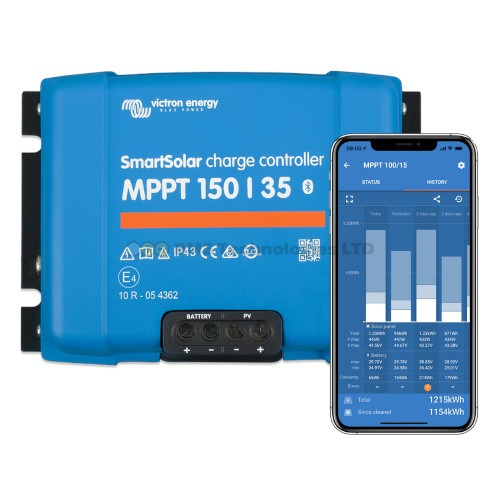
The largest VE.Direct MPPT (the SmartSolar 150/100) handles roughly 1450W at 12V. If your solar array exceeds this — common on larger motorhomes, off-grid homes, or boats — you need a second controller. For example, a 2kW array on a 12V system might use two SmartSolar 150/60 controllers, each handling 1kW.
3. Mixed Panel Types or Voltages
If you have panels with different Vmp (voltage at maximum power) values, they perform poorly when wired together on a single MPPT. Running each panel type on its own controller avoids the mismatch penalty entirely. This is especially relevant when adding new panels to an existing installation where the original panels are no longer available.
4. Redundancy
In critical off-grid systems, two smaller controllers provide redundancy. If one fails, you still have half your solar capacity online while sourcing a replacement.
How to Wire Multiple MPPTs to the Same Battery Bank
The battery-side wiring is straightforward: all MPPT controllers connect to the same battery bank, either directly or via a common bus bar.
Basic Wiring Rules
- Each MPPT has its own independent PV input. Never connect two MPPTs to the same solar string — each controller must have its own dedicated panel(s).
- All MPPTs share the same battery connection. Use a bus bar or battery terminal distribution block. Each MPPT gets its own fused cable run to the bus bar.
- Use equal cable lengths and gauges from each MPPT to the bus bar. Unequal cable lengths create different voltage drops, causing the controllers to see slightly different battery voltages. This leads to one controller doing more work than the other and uneven charge transitions.
- Fuse each MPPT individually. Each controller's positive battery cable should have its own fuse rated at 125% of the controller's maximum output current.
Fuse Sizing for Common Configurations
| MPPT Model | Max Output Current | Recommended Fuse | Minimum Cable (12V) |
|---|---|---|---|
| SmartSolar 100/20 | 20A | 25A | 4mm² |
| SmartSolar 100/30 | 30A | 40A | 6mm² |
| SmartSolar 100/50 | 50A | 60A | 10mm² |
| SmartSolar 150/35 | 35A | 40A | 6mm² |
| SmartSolar 150/60 | 60A | 80A | 16mm² |
| SmartSolar 150/100 | 100A | 125A | 35mm² |
Cable sizes shown are minimum recommendations for runs under 2 metres. For longer runs, increase the gauge — use a cable sizing calculator or consult our MPPT sizing guide for details.
Synchronising Charge Phases: Why It Matters
When multiple MPPTs charge the same battery, they each independently monitor battery voltage to determine which charge phase to use (bulk, absorption, or float). Without synchronisation, you can get this scenario:
- MPPT-1 sees the battery hit 14.2V and enters absorption, reducing its current.
- The voltage dips slightly because of the current reduction.
- MPPT-2 sees the voltage drop and stays in bulk, pushing full current.
- The voltage rises again, MPPT-1 adjusts, and the two oscillate back and forth.
This "hunting" behaviour means the battery never gets a clean absorption phase, which can reduce lithium cycle life and prevent lead-acid batteries from reaching a full charge. The solution is charge synchronisation.
Option 1: VE.Smart Networking (No GX Device Required)
VE.Smart Networking uses Bluetooth to create a wireless network between Victron SmartSolar MPPTs. All SmartSolar VE.Direct controllers support this feature — no additional hardware is needed beyond the controllers themselves.
How to Set Up VE.Smart Networking
- Open the VictronConnect app on your phone.
- Connect to the first MPPT via Bluetooth.
- Go to Settings → VE.Smart Networking.
- Tap Create Network and give it a name (e.g., "Solar Array").
- Disconnect and connect to the second MPPT.
- Go to Settings → VE.Smart Networking.
- Tap Join Existing Network and select the network you created.
- Repeat for any additional MPPTs.
Once networked, the controllers share battery voltage and current data over Bluetooth. They will synchronise their charge phase transitions — when one enters absorption, all enter absorption simultaneously. One controller is automatically elected as the "master" for charge state decisions.
Adding a Smart Battery Sense or SmartShunt
For even better accuracy, add a Victron Smart Battery Sense or SmartShunt to the VE.Smart Network. These devices measure voltage directly at the battery terminals, eliminating cable drop errors. The MPPTs then use this precise voltage reading instead of their own terminal voltage. This is particularly valuable when cable runs are long or cable gauges are marginal.
VE.Smart Networking Limitations
- Bluetooth range is limited — typically 5–10m in practice, less through metal walls or enclosures.
- Maximum recommended network size is about 10 devices.
- If Bluetooth signal is lost, each MPPT reverts to independent operation.
- No remote monitoring — you can only check status when physically near the controllers.
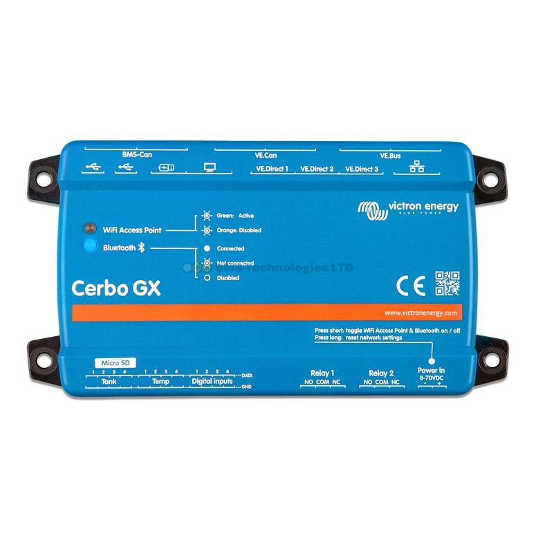
Option 2: DVCC via a Cerbo GX (Recommended for Larger Systems)
For systems with a Cerbo GX or other GX device, DVCC (Distributed Voltage and Current Control) provides robust charge synchronisation over wired connections. DVCC works with both VE.Direct and VE.Can MPPTs.
How DVCC Works
When DVCC is enabled on the GX device, it takes central control of all connected charge sources. Rather than each MPPT independently deciding its charge state, the GX device calculates the optimal charge voltage and current limit for the entire system, then instructs each MPPT accordingly.
This is particularly powerful when combined with a compatible BMS (Battery Management System). The BMS tells the GX device exactly what voltage and current the battery wants, and the GX device distributes this across all MPPTs. The result is perfectly coordinated charging with no hunting or oscillation.
Enabling DVCC
- Connect all MPPTs to the Cerbo GX (via VE.Direct cables or VE.Can bus).
- In the GX device menu, navigate to Settings → DVCC.
- Enable DVCC.
- If you have a compatible BMS, enable SVS (Shared Voltage Sense) and SCS (Shared Current Sense).
- Set the charge current limit if you want to cap total charge current to the battery.
With DVCC active, the GX device's VRM portal shows each MPPT's individual contribution and the total combined solar harvest. For more on GX device setup, see our Cerbo GX setup guide.
DVCC vs VE.Smart Networking
| Feature | VE.Smart Networking | DVCC (via GX) |
|---|---|---|
| Connection | Bluetooth (wireless) | VE.Direct or VE.Can (wired) |
| Requires GX device | No | Yes |
| Charge sync | Yes | Yes (more robust) |
| BMS integration | No | Yes |
| Remote monitoring | No | Yes (via VRM) |
| Reliability | Good (Bluetooth dependent) | Excellent (wired) |
| Max controllers | ~10 | 25+ (VE.Can) |
| Cost | Free (built-in) | Requires Cerbo GX (~£230–£280) |
Important: Do not use VE.Smart Networking and DVCC simultaneously for the same charge synchronisation purpose. If your MPPTs are connected to a GX device with DVCC enabled, disable VE.Smart Networking on those controllers. Running both can cause conflicting charge instructions.
Cable Sizing for Multi-MPPT Systems
When running multiple MPPTs, the combined charge current at the battery bus bar can be substantial. Size your cables and bus bar for the total combined current, not just individual controller outputs.
Example: Two SmartSolar 100/30 Controllers at 12V
- Each MPPT outputs up to 30A → total potential battery current is 60A.
- Each MPPT-to-bus-bar cable: 6mm² minimum (for runs under 2m).
- Bus bar to battery cable: 16mm² minimum (carrying up to 60A combined).
- Bus bar fuse (battery side): 80A mega fuse.
- Individual MPPT fuses: 40A each.
Common Mistakes with Multiple MPPTs
Mistake 1: Unequal Battery Cable Lengths
This is the number one error. If one MPPT has a 1m cable to the battery and the other has a 3m cable, they'll read different battery voltages due to cable voltage drop. The MPPT with the shorter cable sees a higher voltage and may enter float prematurely while the other is still in bulk. Use equal lengths and equal gauges for all MPPT-to-battery connections.
Mistake 2: Sharing PV Input Between Controllers
Never connect two MPPT controllers to the same solar panels. Each MPPT must have its own dedicated PV input. Sharing a PV source between two MPPTs causes them to fight over the power point, dramatically reducing harvest and potentially causing instability.
Mistake 3: No Synchronisation
Running multiple MPPTs on the same battery without any synchronisation (no VE.Smart Network, no DVCC) technically works, but leads to inefficient charging with phase hunting. Always set up synchronisation via one of the two methods described above.
Mistake 4: Undersized Bus Bar or Common Wiring
Your bus bar and the cable from the bus bar to the battery must handle the total combined current of all MPPTs. Two 30A controllers require 60A capacity in the common path. Three 50A controllers need 150A capacity. Undersized common wiring creates a fire risk.
Practical Multi-MPPT Configurations
| Scenario | Recommended Setup | Sync Method |
|---|---|---|
| Campervan with 2 × 200W panels (different tilts) | 2 × SmartSolar 100/20 | VE.Smart Networking |
| Motorhome with 4 × 200W roof panels | 2 × SmartSolar 100/30 | DVCC via Cerbo GX |
| Boat with roof + arch panels | 2 × SmartSolar 150/35 | VE.Smart or DVCC |
| Off-grid cabin with 3kW array | 2 × SmartSolar 150/85 (VE.Can) | DVCC via Cerbo GX |
| Large off-grid home with 6kW array | 3 × SmartSolar 250/85 (VE.Can) | DVCC via Cerbo GX |
Summary
Multiple Victron MPPTs on the same battery bank is a fully supported, well-proven configuration. Wire each MPPT to its own dedicated solar input, connect all battery outputs to a common bus bar with equal cable lengths, fuse each controller individually, and set up charge synchronisation using either VE.Smart Networking (Bluetooth, no extra hardware) or DVCC (via a Cerbo GX, more robust). For systems with a GX device, DVCC is the preferred synchronisation method. For simpler setups without a GX device, VE.Smart Networking does the job well.