A properly wired consumer unit is the backbone of a safe 230V AC system in a motorhome. It distributes power to your circuits, provides overcurrent and RCD protection, and interfaces with your Victron MultiPlus for seamless switching between shore power and inverter operation. This guide walks through consumer unit selection, circuit layout, cable sizing, and the wiring connections specific to a Victron motorhome installation.
Applicable Standards
Motorhome electrical installations in the UK should comply with:
- BS EN 1648-1: Habitation requirements for leisure accommodation vehicles — electrical installations (low voltage)
- BS 7671: IET Wiring Regulations (general reference for good practice)
- NCC standards: if the motorhome carries an NCC approval
While BS EN 1648 is the primary standard for motorhomes, it references BS 7671 extensively. A qualified electrician familiar with both documents should inspect the finished installation.
Choosing a Consumer Unit
Size and IP Rating
Space is always limited in a motorhome. Look for a compact consumer unit that fits your available mounting area. The unit needs to be accessible for resetting tripped MCBs and RCDs, so avoid burying it behind panels where it cannot be reached without tools.
For indoor mounting (inside a wardrobe, under a seat, or in a dedicated electrical bay), a minimum of IP40 is recommended. If the unit is mounted in an area exposed to condensation or splashing (near an external locker door, for example), use IP65 rated equipment.
Material
BS 7671 Amendment 2 requires consumer units in domestic premises to be non-combustible (metal enclosures). While motorhomes are not technically domestic premises, using a metal consumer unit is good practice and highly recommended. Plastic consumer units are acceptable under BS EN 1648 but offer less fire resistance.
Number of Ways
A typical motorhome needs 4 to 8 circuits. A 6-way or 8-way consumer unit gives room for current circuits plus spare ways for future additions. It is always better to have one or two spare ways than to run out of space.
Recommended Circuit Layout
Here is a typical circuit layout for a well-equipped motorhome with a Victron MultiPlus:
| Circuit | MCB | Cable | Notes |
|---|---|---|---|
| Lighting | 6A Type B | 1.0mm² or 1.5mm² | LED lighting has very low draw |
| Kitchen sockets | 16A Type B | 2.5mm² | Microwave, kettle, toaster |
| General sockets | 16A Type B | 2.5mm² | Living area, bedroom |
| Water heater | 16A Type B | 2.5mm² | Dedicated circuit if >1kW |
| Bathroom (if fitted) | 6A Type B | 1.5mm² | Towel rail, mirror light |
| Air conditioning | 16A Type C | 2.5mm² | Type C for compressor inrush |
| Charger / converter | 6A Type B | 1.5mm² | 12V charger if separate from MultiPlus |
| Spare | — | — | Future use |
Circuit Priorities
When running on the inverter, your total power is limited by the MultiPlus output rating. A MultiPlus 12/2000 delivers roughly 1,600W of real power. You cannot run a kettle (2kW) and a microwave (800W) simultaneously on that inverter. Design your circuits so that essential loads (lighting, fridge, USB charging) are separate from high-draw loads (kitchen sockets), and educate users about the inverter's limits.
RCD Protection
Minimum Requirements
BS EN 1648 requires 30mA RCD protection on all AC circuits in a motorhome. You have two approaches:
- Split-load consumer unit: two (or more) RCDs, each protecting a group of circuits. If one RCD trips, the other group remains live. This is the recommended approach.
- Single RCD: one RCD protects all circuits. Simpler and cheaper, but any fault trips everything. Not ideal when you want lighting to survive a socket circuit fault.
- RCBOs: individual combined RCD/MCB units per circuit. Each circuit is independently protected. The most expensive option but provides the best selectivity and eliminates nuisance tripping issues.
For detailed guidance on RCD types, see our RCD and MCB requirements guide.
Recommended Split-Load Design
A practical split-load arrangement for a motorhome:
- RCD 1 (40A, Type A): lighting, bathroom, charger — essential circuits that you want to keep live
- RCD 2 (40A, Type A): kitchen sockets, general sockets, water heater, air conditioning — higher-draw circuits more likely to cause a trip
Use Type A RCDs as a minimum. See our guide on why Type A matters for inverter installations.
Main Switch
The consumer unit should have a double-pole main switch — one that breaks both line and neutral simultaneously. This is a BS EN 1648 requirement for motorhomes. The main switch should be rated at least equal to the maximum incoming supply current (typically 16A for a UK campsite hook-up, or higher if the MultiPlus output exceeds this).
A 40A or 63A double-pole main switch is standard and provides adequate capacity for any likely motorhome installation.
Wiring the MultiPlus to the Consumer Unit
AC Output Connection
The MultiPlus AC output (AC Out 1) connects to the consumer unit input. This is the main feed carrying either shore power (passed through by the MultiPlus) or inverter power. The cable must be sized for the maximum current the MultiPlus can deliver:
| MultiPlus Model | Max AC Output Current | Minimum Cable Size | Recommended Cable Size |
|---|---|---|---|
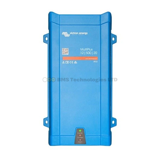
| MultiPlus 12/800/35 | 3.5A | 1.0mm² | 2.5mm² |
| MultiPlus 12/1200/50 | 5.2A | 1.0mm² | 2.5mm² |
| MultiPlus 12/1600/70 | 7.0A | 1.5mm² | 2.5mm² |
| MultiPlus 12/2000/80 | 8.7A | 1.5mm² | 4.0mm² |
| MultiPlus 12/3000/120 | 13.0A | 2.5mm² | 4.0mm² |
Always use three-core cable (line, neutral, earth) for this connection. The earth conductor must be properly sized and connected to the consumer unit earth bar.
AC Input Connection
Shore power connects to the MultiPlus AC input (AC In). This typically comes from a CEE blue 16A inlet socket mounted on the outside of the motorhome, via a cable run to the MultiPlus. Use 2.5mm² three-core cable for a 16A supply. Install a double-pole isolator between the inlet and the MultiPlus so you can disconnect shore power without unplugging the external cable.
AC Out 2 (Non-Essential Loads)
The MultiPlus has a second AC output (AC Out 2) that is only live when shore power is connected. It is disconnected when running on inverter power. Use this for loads you do not want running from the batteries — for example, a high-power water heater or an electric space heater. AC Out 2 can feed a separate small consumer unit or a single dedicated circuit with its own MCB and RCD protection.
Earth Bonding
The MultiPlus ground relay automatically manages the neutral-earth bond. When on shore power, the ground relay opens and the shore supply provides the earth reference. When inverting, the ground relay closes and bonds neutral to earth at the MultiPlus.
The MultiPlus earth terminal must be connected to the consumer unit earth bar with a properly sized earth conductor (minimum 6.0mm² for a 3000VA unit). All circuit earth conductors terminate at the consumer unit earth bar.
Shore Power Inlet and RCD
Inlet Socket
UK motorhomes typically use a CEE 16A blue inlet socket (IEC 60309, 2P+E, 6h position) mounted on the outside of the vehicle. This is the standard campsite hook-up connector. The inlet must be IP44 rated or better for external mounting.
Upstream RCD
Some installers fit an RCD between the shore power inlet and the MultiPlus AC input. This provides additional protection for the feed cable running through the vehicle. However, it is not strictly required by BS EN 1648 if the consumer unit already has RCD protection on all circuits. The campsite supply bollard will also have its own RCD protection.
If you do fit an inlet RCD, use a time-delayed (Type S) unit rated at 100mA. This ensures that a fault on one of your circuits trips the 30mA RCD at the consumer unit first, rather than the inlet RCD tripping and taking out the entire supply. This selectivity prevents unnecessary loss of power to the whole vehicle.
Cable Routing
Separation from DC Wiring
Keep 230V AC cables physically separated from 12V DC cables. Where they must cross, cross at right angles. If they must run in parallel, maintain a minimum separation of 75mm or use a physical barrier (cable trunking, conduit, or a plywood divider).
Cable Support
All cables must be supported and secured at regular intervals. In a motorhome, vibration from driving can chafe unsecured cables against sharp edges. Use cable clips, P-clips, or trunking throughout. Pay particular attention to where cables pass through bulkheads — fit rubber grommets to prevent chafing on metal edges.
Cable Identification
Mark all 230V AC cables clearly. Use the correct colour coding: brown (line), blue (neutral), green/yellow (earth). Where cables are hidden behind panels, label each end with the circuit name and the consumer unit way number.
Example Wiring Diagram Overview
The overall wiring flow for a typical Victron motorhome 230V system is:
- CEE 16A inlet (outside of vehicle) with IP44 socket
- Double-pole isolator (optional but recommended)
- MultiPlus AC In — shore power input
- MultiPlus AC Out 1 — main output (shore power or inverter)
- Consumer unit — double-pole main switch, split-load RCDs, individual MCBs
- Circuits — lighting, sockets, water heater, etc.
- MultiPlus AC Out 2 (optional) — to a separate MCB/RCD for shore-power-only loads
Common Mistakes
- Undersized feed cable: the cable from MultiPlus to consumer unit must be rated for the MultiPlus maximum output current, not the campsite supply current
- Missing earth bond: not connecting the MultiPlus earth terminal to the consumer unit earth bar — the ground relay has nothing to bond to
- Single RCD for everything: one tripped RCD means no lighting, no fridge, no phone charging. Use a split-load design
- No double-pole isolation: a single-pole main switch does not meet BS EN 1648 requirements
- Forgetting AC Out 2 protection: the AC Out 2 circuit still needs its own MCB and RCD protection, even though it is only live on shore power
- Mixing up AC In and AC Out: connecting shore power to the output terminals and the consumer unit to the input terminals will not work and may damage equipment
Testing and Certification
After installation, the following tests should be carried out:
- Continuity of all protective conductors (earth continuity)
- Insulation resistance between live conductors and earth (minimum 1M ohm)
- Polarity checks on all circuits
- RCD trip time testing in both shore power and inverter modes
- Functional check of the MultiPlus ground relay operation
A qualified electrician should provide an Electrical Installation Certificate or equivalent documentation. Keep this with the motorhome's paperwork — it may be required for insurance purposes or NCC compliance.
Recommended Products
Use our price comparison tool to find the best UK prices on the MultiPlus range. For a typical motorhome, the MultiPlus 12/2000/80 or MultiPlus 12/1600/70 are the most popular choices, offering a good balance between power output, charger capacity, and physical size. Pair with a SmartSolar MPPT controller and SmartShunt for a complete system.